NSR250.net Forums Logo: Honda NSR 250 Forums, Classifieds and Service Manual in English. Covering All Honda NSR 250 MC16, MC18, MC21 and MC28 models
NSR250.net Forums

#
 
#
 
Race Lubricants

  • NSR250 Forums Index ‹ Members' NSR Builds
  • Members Content
  • Members Garage
  • Subscription
  • Transactions
  • FAQ
  • Search
  • Register
  • Log in

NSR250 MC18 R5K Engine Rebuild


Reply to topic   printer-friendly view
Page 3 of 3  Goto page Previous  1, 2, 3 Download Topic


philup_7@hotmail.com

 
Posts: 93
Joined: 09 Oct 2018

Location: Worcestershire
    Send private message View user's profile
    Reply with quote  

Sun Mar 29, 2026 9:37 am » Post: #31 » Download Post

RH Side Crankcase Build Cont’d
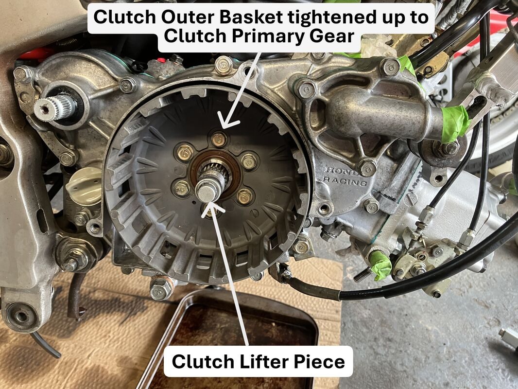
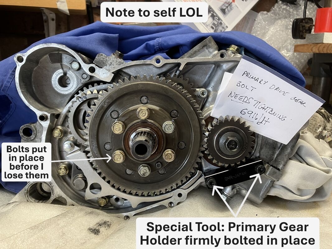
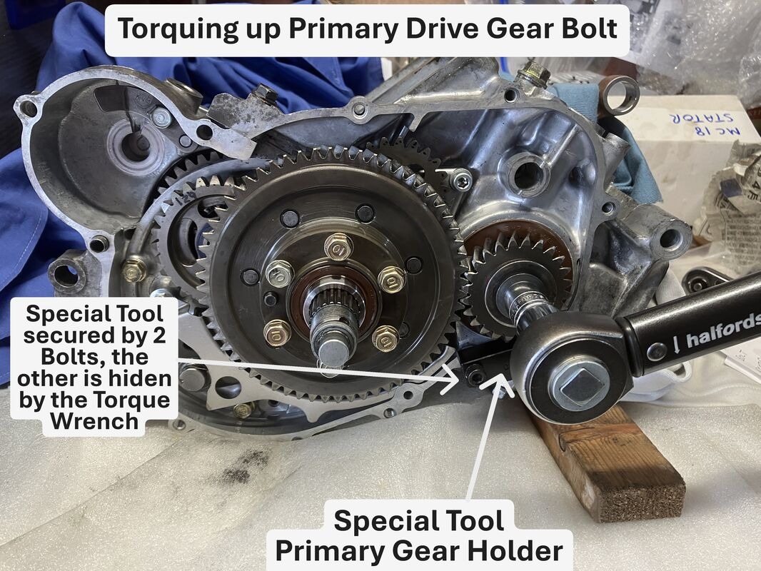
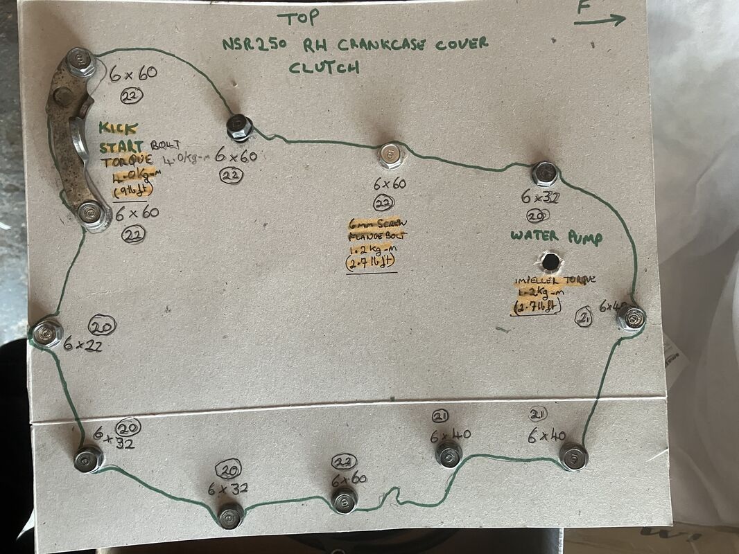
Message to self, reminder of torquing up Primary Drive Gear Bolt, a must in my case if it isn’t done straight away.
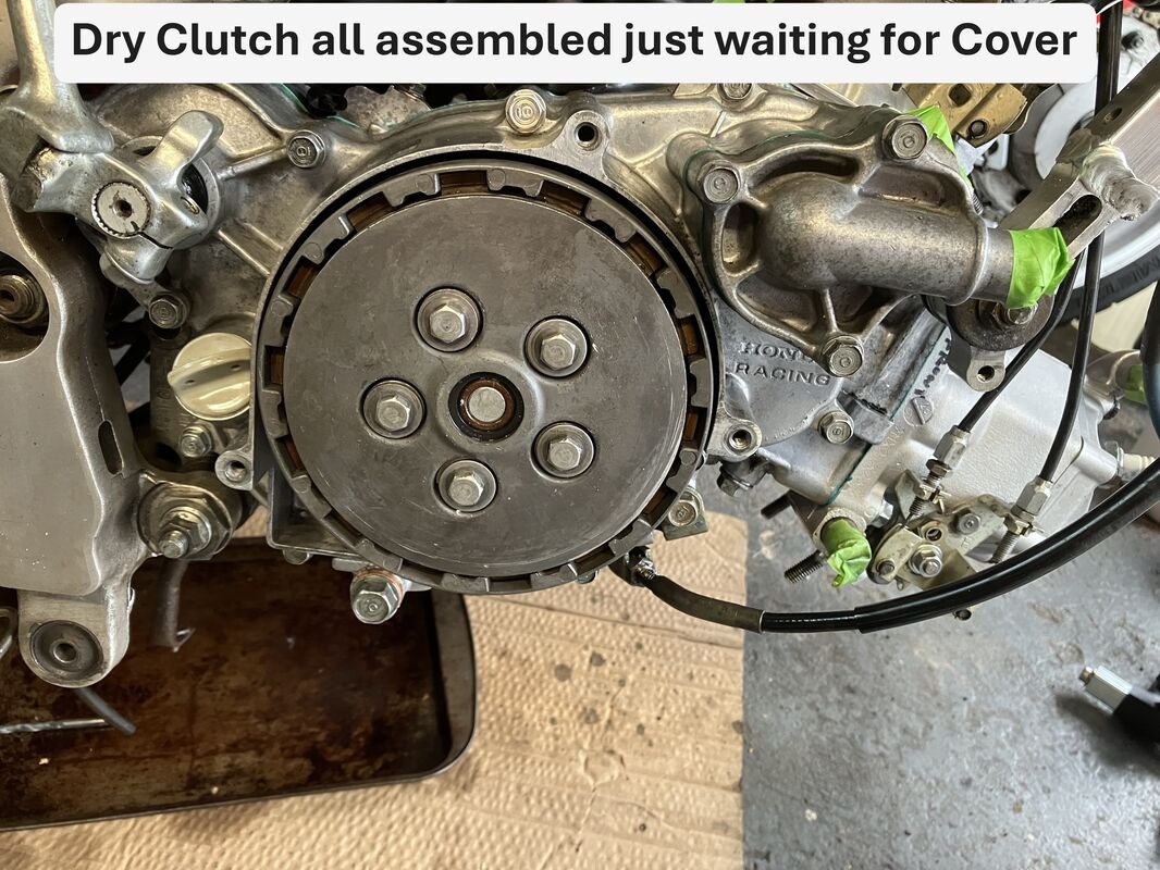
The Clutch Primary Gear was mounted on the Mainshaft together with its associated Spacers/Collars, Bearings & Oil Seal, please see http://www.nsr250.net/forums/viewtopic.php?t=15439&highlight= for more detail.


Thank goodness for Cardboard it has so many uses!


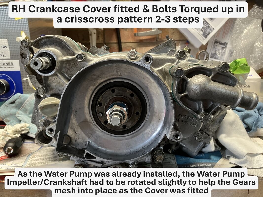
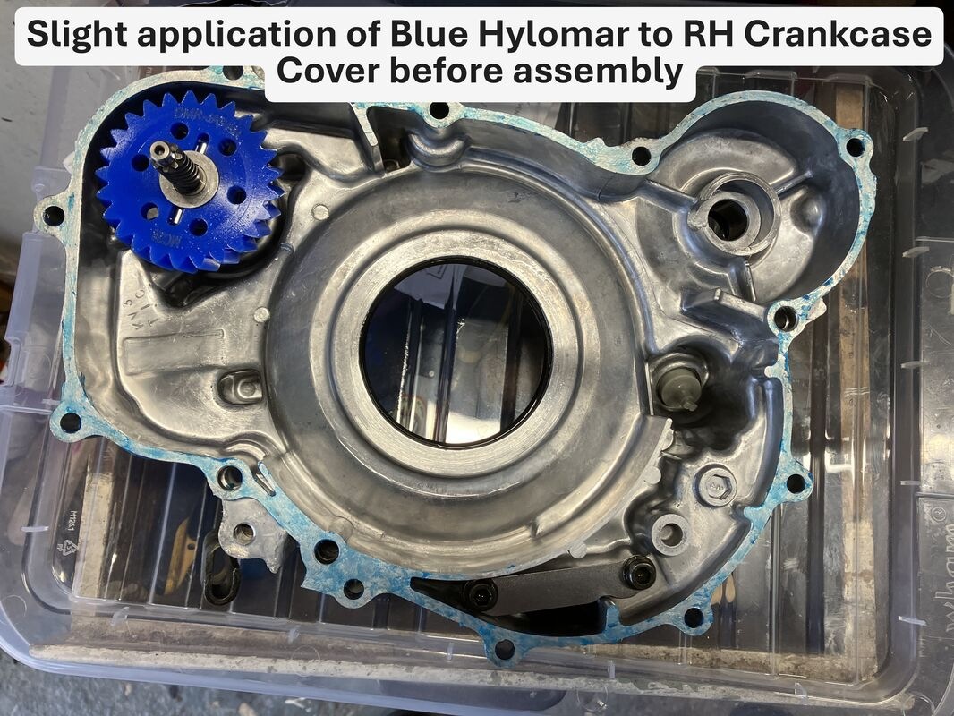
Slight application of Blue Hylomar to RH Crankcase Cover (love the stuff, been using it since the 60s!!! well it was ok for Rolls Royce so who am I to argue, ok it may have been used on Jet Engines LOL).
The water pump wasn’t removed as it was rebuilt very recently.


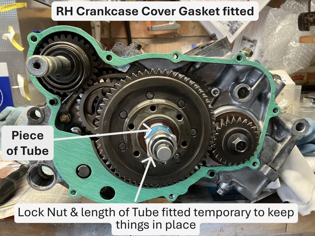
A new Sump Washer & Crankcase Cover Gasket was fitted, the Kick Starter & Crankcase Cover to Clutch Primary Gear Oil Seals were left as is, as they had been replaced very recently.
A slight manipulation of the Water Pump Impeller/Crankshaft was required to help mesh the Gears whilst trying to get the Crankcase Cover home before bolting everything up.


Back to top


philup_7@hotmail.com

 
Posts: 93
Joined: 09 Oct 2018

Location: Worcestershire
    Send private message View user's profile
    Reply with quote  

Mon Mar 30, 2026 11:41 am » Post: #32 » Download Post

Checking Reed Valve
Although I was now ready to fit the Reed Valves, Stuffers, Gasket and Manifold/Insulator, I had previously inspected the Reed Valves and one had a slight gap in one of the Reed Petals which needed to be sourced & sorted first.
Note: A bit difficult to get a good camera shot of the gapping, holding it up against the sunlight hopefully you can just make it out. I would have tried a torch behind it, but I ran out of hands I’m afraid.


Dismantle offending Reed Valve Petals.


Re-fitting the new Petals sourced from WEBIKE, it’s ok to re-fit the screws using the existing spring washers apparently, however, I must own up to putting the very slightest of dabs of Loctite 243 on the threads to make sure.


Back to top


philup_7@hotmail.com

 
Posts: 93
Joined: 09 Oct 2018

Location: Worcestershire
    Send private message View user's profile
    Reply with quote  

Mon Mar 30, 2026 10:36 pm » Post: #33 » Download Post

Carb Manifold/Insulator Installation
Applied a little Blue Hylomar on the Reed Valve Gasket and placed it on the mating surface followed by the Reed Valves and Stuffers.


The Manifold/Insulator had previously been checked for any Cracks, Perishing, Splits and Warping (warping was checked with a straight edge across the mating surface held against the light), and although it looked good I’m afraid I succumbed & applied a little bit of HONDA Threebond to the mating surface for good measure.
Fitting the Manifold/Insulator I paid very careful attention to its tightening sequence, starting by hand and then gradually tighten up bolts to 5 lb/ft, 60 lb/in in several stages (didn't want to warp it).
Note: Made sure the longer 32mm Bolts went on the outer Edges of the Insulator, tightening sequence number Bolts 5-8.


Back to top


philup_7@hotmail.com

 
Posts: 93
Joined: 09 Oct 2018

Location: Worcestershire
    Send private message View user's profile
    Reply with quote  

Wed Apr 01, 2026 5:55 pm » Post: #34 » Download Post

Piston/Cylinder/Head Fitment
2 ‘Bs’ or not 2 ‘Bs’ that is the question LOL!.
The 2 Cylinders with Marks ‘B’ stamped on them had been sent away some time ago for some remedial work and Nikasil plating.
You can tell how NEW/NAIVE or JUST LUCKY I am to all of this, as the following came as a bit of a surprise. I assumed (yes assume stands for making an ass out of you and me LOL) quite wrongly, that the Cylinders when Nikasil plated would be automatically as per HONDA’s Cylinder & Piston Selection Table dimensions.
A ha! not necessarily the case, as I only found out the hard way by asking a few probing questions.

Although on the face of it, the Cylinder and Piston selection Table is a good place to start, there are some pitfalls that one should be mindful of when carrying out the selection process to which I was completely unaware of, hence the NEW/NAIVE or JUST LUCKY comment.

The following is my attempt to put some thoughts down on this process as follows, so hopefully it makes some sense (would be a first for me!!):
    • It may not be all as it seems: The Cylinder Marking stamp of ‘A’, ‘B’ or ‘C’ on the side of the Cylinders only indicate the bore size when it originally came out of the factory, if they have been re-plated, then they may be a different Bore Diameter to that stamped on the side of the Cylinders (for example, thicker Nikasil plating applied to bring it back to STANDARD NSR125 Cylinders size of 54.00mm).

    • Recommendation: Firstly provide the PISTONS to be used with the CYLINDERS to be Nikasil plated to the Service Supplier to make absolutely sure everything will be ok before re-plating process.

    • Another guess: It’s only an educated guess, that there would be issues if you tried to use say PISTON ‘B’ (largest available Piston) in a re-plated Cylinder ‘B’ (smallest Bore Size), but you have to check that out with the Service Supplier.

End of confusion or my rant LOL!!

Fortunately for me, following a dialogue with the Service Supplier, I obtained HONDA Pistons Marked ‘D’ for a 54.0mm Bore without realising at the time what had taken place, as ‘B’ marked Cylinders should have ‘NO MARK’ Pistons, another lesson learned and chalked up to experience.


Applied a bit of heat to Piston to help slide Gudgeon Pin in makes life so much easier.


Ready to go Base Gasket on and of course with a bit of Hylomar.


Made sure Rings were positioned to abut the Piston locating Pins.


I decided to install the RC Valves before installing the Cylinder Barrels on the Crankcase, as I felt it would be a lot easier to do and especially as I had obtained T2’s special tool for Cylinder Nuts (can’t remember where from, although WEBIKE do supply them product code T2-Ti-SN-T) which makes the job so easy.
Installing the Cylinder is not an easy job particularly if you have Arthritic Hands & Fingers like me, I slid the Cylinder Barrel down over the Piston & Rings whilst holding Piston & using Finger Nails at the same time to depress the Rings and making sure they don’t move (‘like sticking your finger in your ear and singing ting-a-ling-a-loo’. Don’t try this at home LOL) and remain tucked in and abutting the Pistons locating Pins.
Et voila as they say in French! one Cylinder Barrel on and now to Torque it up.


Back to top


Andy
Site Admin
 
Posts: 12101
Joined: 19 Jan 2004

Location: Devon, UK
1991 Honda NSR250 MC21
    Send private message View user's profile
    Reply with quote  

Wed Apr 01, 2026 6:16 pm » Post: #35 » Download Post

philup_7@hotmail.com wrote:


Looks like you snuck a pair of HRC rectifiers (stuffers) in there on quiet! Wink
_________________
Andy.
NSR-WORLD.COM

Please keep all responses to Forum posts on the Forum so that others may benefit.

Please DO NOT PM me for technical advice. My time is precious, and you will probably receive a faster response on the Forum anyway.


Check us out on Facebook! Please "like" our page!
Back to top


philup_7@hotmail.com

 
Posts: 93
Joined: 09 Oct 2018

Location: Worcestershire
    Send private message View user's profile
    Reply with quote  

Thu Apr 02, 2026 4:32 pm » Post: #36 » Download Post

Caught LOL Very Happy Very Happy
Back to top


philup_7@hotmail.com

 
Posts: 93
Joined: 09 Oct 2018

Location: Worcestershire
    Send private message View user's profile
    Reply with quote  

Sun Apr 05, 2026 12:09 pm » Post: #37 » Download Post

Leak Down Testing


Before installing the Flywheel & Clutch I decided to conduct a Leak Down Test, however, I needed to build one first. The following is my basic attempt of a Leak Down Tester, not the best thing in the world I admit, which was made from the following:
• ¼” BSP fittings (some parallel fittings BSPP & some Tapered BSPT) including lock nuts;
• Inflator Bulb Air Pump;
• Low Pressure Gauge 0/15 PSI;
• Nitrile Rubber O-Rings;
• 1/4" BSP Bonded Seal Sealing O-Ring Washers;
• 40mm Plumbing Socket Plugs;
• Fabricated Exhaust & 2T Oil Pump Blanking Plates;
• Not to forget some PTFE Gas Tape (Yellow).


I thought it useful to have some notes just in case I decided to do it again further down the road, by which time I would have completely forgotten everything!
A lot of these notes were cribbed off other sites (thanks to NSR WORLD, TYGA, T2 Racing in advance), so I hope they are correct and I haven’t done anyone a disservice with any inaccuracies, so apologies in advance if I have, please let me know!

    1. The 2 Exhaust Ports were sealed using 2 x 5.7mm Rubber O-Rings together with 2 pre-fabricated Exhaust Blanking Plates and tightened up on the Exhaust Port Studs;
    2. Additional Centre Bearing Oilway (for later MC21s or MC28s) where the 2T Oil Pump sits was blanked off with a pre-fabricated Blanking Plate & O-Rings;
    3. Leak Down Tester was installed as follows:
      a. the Pressurising Bung is inserted into left side of the Carburettor Insulator and its Band tightened to secure it;
      b. Second blanking Bung inserted into the right side of the Carburettor Insulator and its Band tightened to secure it;
      c. Spark Plugs tightened to seal the Cylinder Heads;

    4. Crankshaft was rotated so that the Piston of the Chamber being pressurised is it at Bottom Dead Centre (BDC);
    5. Hand Pump in the Left Crankcase Chamber is pressurised (T2-Racing advise 5 PSI, TYGA advises 10 PSI, members of NSR-WORLD seem to use 7 PSI), I went middle of the road at 7 PSI;
    6. Monitored over the 5 Minute period to see if there were any pressure drop (T2-Racing advises no pressure drop at all, or it's less than 0.5 PSI over 5 Minutes);
    7. Process 2-6 above was repeated for the Right Crankcase Chamber.


Note: If the leakage is greater than 0.5 PSI:
    1) check the Gauge on the side that’s not being pressurised to see if there has been no leakage thru the Centre Seal (although Andy NSR-WORLD says ‘It's not uncommon to see pressure bleed one way and not the other, because of the nature of the labyrinth seal. In an ideal world it should hold full pressure both ways though’) http://www.nsr250.net/forums/viewtopic.php?t=15172&highlight=leak+test;
    2) made up some soapy water solution (ROCOL leak detector spray, Shaving Foam are alternatives) and sprayed onto the most likely parts where a leakage could occur, namely the Carburettor Insulator, Left and Righthand Crankshaft Seals, Crankcase joint etc.. to detect where the leakage is occurring.
    3) depending where the leak occurs the Engine may require to be completely stripped and re-built to eradicate the leak.


The left-hand Crankcase lost some pressure, but was within acceptable limits, however, the right-hand chamber seemed to lose more than it should (unfortunately, although I did write it all down the timings and pressure loss they seem to have got lost somewhere) so I applied the soap suds to everywhere I could think to see where there could be a leak to no avail.
I really should have had another Guage in the none pressurised Chamber to see if there was any pressure bleed from the pressurised Chamber into the other.

This will be rectified on the Mk2 Leak Down Tester or as they say on Television ‘Lessons to be Learned’ or more put more bluntly, I should have paid more attention to Note 1 above!!!.


Back to top


philup_7@hotmail.com

 
Posts: 93
Joined: 09 Oct 2018

Location: Worcestershire
    Send private message View user's profile
    Reply with quote  

Sat Apr 11, 2026 10:40 am » Post: #38 » Download Post

Installing Flywheel
Following installation of the Stator assembly, the Flywheel was located on the Woodruff Key and I used a Universal Flywheel Holder with a homemade extender bar wedged on the ground to torque it up. The Pickups were then installed and the cables routed back to their original connectors.
MC28 Neutral Switch/MC 21 GPS Installation
Using HONDA’s:
    • MC28 Neutral Switch wire, this was routed as shown and connected to the existing MC18 R5K (Neutral Light Switch light Green/Red wire) Bullet Connector in the main loom located by the Regulator. The MC28 Neutral Switch wire was just about long enough.
    • MC21 GPS (Gear Position Sensor), the separate light Green/Red wire (Note: PROTECH’s GPS-01 gear position sensor model 11609 in the Picture is White/Green wire, but I think in reality it’s nearer light Green/Pinkish) can be connected directly to the MC18 R5K (Neutral Light Switch light Green/Red wire) Bullet Connector in the main loom located by the Regulator and the Block Connector stowed away & secured, no connection necessary unless you want to install an aftermarket Gear Position Indicator. Not sure whether the length of HONDA’s MC21 GPS/PROTECH’s GPS-01 wire is long enough to connect back to the Bullet connector and may require extending.

The existing MC18 Neutral Light Wire which is located in the same sub loom as the Pick up wires and was left dangling for the time being.
Note: the MC21 GPS Wire will be a lot fatter as it has 7 wires instead of the MC28’s Neutral single wire.


An extra cut out was required in the Flywheel Cover to enable the Neutral/GPS wire to pass thru it. The old MC18 Neutral Wire was clipped out of the way to the Flywheel Cover.

Back to top


philup_7@hotmail.com

 
Posts: 93
Joined: 09 Oct 2018

Location: Worcestershire
    Send private message View user's profile
    Reply with quote  

Mon Apr 13, 2026 4:59 pm » Post: #39 » Download Post

Dry Clutch Assembly
This is the point where I remembered that we shouldn’t have put the Flywheel Cover back on, as we were going to use the Universal Flywheel Holder on the Flywheel to torque up the Bolts on the Clutch side, oh well, not for the last time me thinks!!
Clutch Outer Basket mounted & the 6 Bolts torqued up in a crisscross pattern 2-3 steps.


Clutch Inner Basket, Clutch Plates assembled (Note: Although it’s advisable to replace the Rubber Dampers on the Damper Disk, we had only just replaced them recently so we didn’t change them), Thrust Washer & Locking Nut torqued up & staked.


New ‘O’ Ring fitted onto the Clutch Lifter Piece, might as well as done everything else. It's a bit reminiscent of changing the Seals on the Brake/Clutch Master Cylinders!!!


Clutch Lifter Rod, Steel Ball, Lifter Piece, Pressure Plate, Springs & Bolts assembled and Bolts tightened up in a crisscross pattern several times then torqued up.
Note: Both the Clutch Lifter Rod ends and the Steel Ball were coated with a little high melting point Grease.


Back to top


Reply to topic   printer-friendly view
Page 3 of 3  Goto page Previous  1, 2, 3 Download Topic

Members' NSR Builds

You cannot post new topics in this forum
You cannot reply to topics in this forum
You cannot edit your posts in this forum
You cannot delete your posts in this forum
You cannot vote in polls in this forum
You cannot attach files in this forum
You cannot download files in this forum

  • NSR250 Forums Index
  • All times are GMT
Powered by phpBB © 2001, 2005 phpBB Group


Hosted by NSR250dotNET © 2008 NSR250dotNET